Difference between revisions of "RC and Servo Support"
(Tag: Visual edit) |
(Removed sold out Spektrum controller.) (Tag: Visual edit) |
||
| (5 intermediate revisions by 3 users not shown) | |||
| Line 1: | Line 1: | ||
| − | |||
| − | |||
==RC Basics== | ==RC Basics== | ||
| − | The two main parts to a RC communication | + | The two main parts to a RC communication are the transmitter and the receiver. The RC transmitter outputs the signal while the receiver receives the signal. This signal can be used for many purposes but we will focus on servos and other loads. RC systems have from 2 to 10+ channels (i.e. a 4 channel radio can control 4 servos). RC receiver outputs are simply a ~1.5ms pulse about every 20ms. This 20ms is measured from the rising edge of the signal to the rising edge of the next. This allows for wireless communication to your servo. The 1.5ms pulse is varied from ~1.0ms to ~2.0ms to give the full range of your device. The 20ms in-between pulses can vary a little, but if it's too long, the servos will become sluggish. The closer to 20ms you can get the better. Below are some images of a servo pulse. |
[[File:RC1.gif|center|thumb]] | [[File:RC1.gif|center|thumb]] | ||
[[File:RC2.gif|center|thumb]] | [[File:RC2.gif|center|thumb]] | ||
| Line 67: | Line 65: | ||
You can use an integrated Sabertooth 2x5, Sabertooth 2x12, Sabertooth 2x25, Sabertooth 2x32, or Sabertooth 2x60 motor controller. Both motor controllers have an RC mode. Both Motor controllers are dual channel, so they can be used to mix you radio signals for single stick skid steering or they can operate independently. These controllers works great and are easy to hook up and get running. These controllers also supply 5V to drive your receiver. The 5V supply is 1A switching supply, so it should only be used for the receiver with no additional loads such as heavy duty servos plugged into the receiver (you will want to use a separate 5V supply if you want to add heavy duty servos or many light duty servos (can draw max of 850mA since the receiver will sometimes draw 150mA) to the other channels of the receiver. We also carry the Syren 10, 25, 50 motor controllers for those who only want to drive one motor and save a little money from the dual motor controllers. | You can use an integrated Sabertooth 2x5, Sabertooth 2x12, Sabertooth 2x25, Sabertooth 2x32, or Sabertooth 2x60 motor controller. Both motor controllers have an RC mode. Both Motor controllers are dual channel, so they can be used to mix you radio signals for single stick skid steering or they can operate independently. These controllers works great and are easy to hook up and get running. These controllers also supply 5V to drive your receiver. The 5V supply is 1A switching supply, so it should only be used for the receiver with no additional loads such as heavy duty servos plugged into the receiver (you will want to use a separate 5V supply if you want to add heavy duty servos or many light duty servos (can draw max of 850mA since the receiver will sometimes draw 150mA) to the other channels of the receiver. We also carry the Syren 10, 25, 50 motor controllers for those who only want to drive one motor and save a little money from the dual motor controllers. | ||
| − | *<sdr item id=851> | + | *<sdr item id=851> Sabertooth 2x5</sdr item> |
| − | *<sdr item id=1155> | + | *<sdr item id=1155> Sabertooth 2x12</sdr item> |
| − | *<sdr item id=822> | + | *<sdr item id=822> Sabertooth 2x25</sdr item> |
| − | *<sdr item id=1822> | + | *<sdr item id=1822> Sabertooth 2x32</sdr item> |
| − | *<sdr item id=1225> | + | *<sdr item id=1225> Sabertooth 2x60</sdr item> |
*<sdr item id=847> Syren 10A Motor Controller</sdr item> | *<sdr item id=847> Syren 10A Motor Controller</sdr item> | ||
*<sdr item id=848> Syren 25A Motor Controller</sdr item> | *<sdr item id=848> Syren 25A Motor Controller</sdr item> | ||
| Line 101: | Line 99: | ||
*<sdr item id=2892> FlySky FS-i6X 2.4G 10CH Transmitter & Receiver</sdr item> | *<sdr item id=2892> FlySky FS-i6X 2.4G 10CH Transmitter & Receiver</sdr item> | ||
*<sdr item id=2794> FlySky FS-i6s 2.4G 10CH Transmitter & Receiver</sdr item> | *<sdr item id=2794> FlySky FS-i6s 2.4G 10CH Transmitter & Receiver</sdr item> | ||
| − | |||
*<sdr item id=1030> Spektrum AR6110e DSM2 ML 6CH Fail Safe Receiver</sdr item> | *<sdr item id=1030> Spektrum AR6110e DSM2 ML 6CH Fail Safe Receiver</sdr item> | ||
*<sdr item id=995> Spektrum Remote Receiver Extension - 36 inch</sdr item> | *<sdr item id=995> Spektrum Remote Receiver Extension - 36 inch</sdr item> | ||
==Binding== | ==Binding== | ||
| − | + | Receiver and transmitters when bought together are bound together. If the transmitter gets broke in use then you can bind a new transmitter to the existing receiver. Follow these steps: | |
*Turn off both the receiver and controller | *Turn off both the receiver and controller | ||
| − | *Plug the binding plugs(included with purchase) into the "bind" slot of the receiver | + | *Plug the binding plugs(included with purchase) into the "bind" slot of the receiver |
| − | *Turn on the receiver, there should be | + | *Turn on the receiver, there should be a fast blinking light, this signals waiting for binding |
| − | *Hold the binding button or switch on your controller | + | *Hold the binding button or switch on your controller |
| − | *Turn on the controller | + | *Turn on the controller |
| − | * | + | *The controller will say "RX binding" |
| + | *Once the message is gone it should be ready use | ||
*Check for connection | *Check for connection | ||
| − | *Remove binding | + | *Remove binding plug |
*Restart both and check for connection still | *Restart both and check for connection still | ||
Now you should set your failsafe state, this is done almost identically. | Now you should set your failsafe state, this is done almost identically. | ||
| − | *Turn | + | *Turn on both the receiver and controller |
| − | * | + | *Hold down OK button to enter menu |
| − | * | + | *Go to System Setup |
| − | * | + | *Go to RX Setup |
| − | + | *Go to Failsafe | |
| − | + | *Select channel you want to turn the failsafe on, click ok, turn on to save hold down cancel | |
| − | + | *Once the channels have failsafes saved hold down cancel to save and close the menu | |
| − | + | ||
| − | + | The easiest/safest way to check your failsafe bind was successful, is to set the robot on blocks so the tracks/tires are off of the ground. Then turn on the robot and controller. Drive the robot and while the tracks/tires are spinning turn off the controller. The robot should stop moving. If the robot continues to move the failsafes did not save. If it does stop then the failsafes are saved and the robot is ready for use. | |
| − | + | [[Category:Electrical Engineering]] | |
[[Category:Mechanical Engineering]] | [[Category:Mechanical Engineering]] | ||
Latest revision as of 17:40, 11 May 2021
Contents
[hide]RC Basics
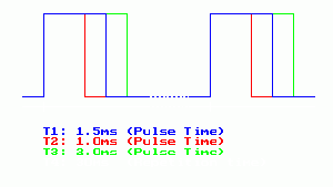
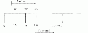
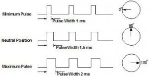
The two main parts to a RC communication are the transmitter and the receiver. The RC transmitter outputs the signal while the receiver receives the signal. This signal can be used for many purposes but we will focus on servos and other loads. RC systems have from 2 to 10+ channels (i.e. a 4 channel radio can control 4 servos). RC receiver outputs are simply a ~1.5ms pulse about every 20ms. This 20ms is measured from the rising edge of the signal to the rising edge of the next. This allows for wireless communication to your servo. The 1.5ms pulse is varied from ~1.0ms to ~2.0ms to give the full range of your device. The 20ms in-between pulses can vary a little, but if it's too long, the servos will become sluggish. The closer to 20ms you can get the better. Below are some images of a servo pulse.
Servos
Servos are DC motors with built in gearing and feedback control loop circuitry; no motor drivers required. Servos are extremely popular with robots, RC plane, and RC boat builders. Most servo motors can rotate about 90 to 180 degrees. Some rotate through a full 360 degrees or more. However, servos are unable to continually rotate, meaning they can't be used for driving wheels, but their precision positioning makes them ideal for robot arms and legs, rack and pinion steering, and sensor scanners to name a few. Since servos are fully self contained, the velocity and angle control loops are very easy to implement, while prices remain very affordable.
All servos have three wires:
- Black or Brown is for ground
- Red is for power (~4.8-6V)
- Yellow, Orange, or White is the signal wire (3-5V).
To use a servo, simply connect the black wire to ground, the red to a 4.8-6V source, and the yellow/white wire to a signal generator (such as from your microcontroller). There are a few micro sized servos that can operate at less, and now a few Hitec servos that operate at much more. The reason for this standard range is because most microcontrollers and RC receivers operate near this voltage. So what voltage should you operate at? Well, unless you have a battery voltage/current/power limitation, you should operate at 6V. This is simply because DC motors have higher torque at higher voltages.
While the black and red wires provide power to the motor, the signal wire is what you use to command the servo. The general concept is to simply send an ordinary logic square wave to your servo at a specific wave length, and your servo goes to a particular angle (or velocity if your servo is modified). The wavelength directly maps to servo angle.
So how do you apply this square wave to your servo? If your robot is remote controlled, your RC receiver will apply the proper square wave for you. If however your robot is running from a microcontroller, you must:
- bring high a digital port
- wait between 1-2ms
- bring low the same digital port
- cycle about every 20ms
With timers or interrupts you will be able to follow the process above without slowing the rest of your program. Some programming languages have servo libraries which make this process much easier.
Servo current operates the same as in a DC motor, except that you now also have a hard to predict feedback control system to contend with. If your DC motor is not at the specified angle, it will suddenly draw large amounts of current to reach that angle.
- Nylon Gears - Nylon gears are most common in servos. They are extremely smooth with little or no wear factors. They are also very lightweight, but lack in durability and strength.
- Karbonite Gears - Karbonite gears are a reinforced plastic composite material used in Hitec RC servos that show almost 5 times the strength of nylon gears and also better wear resistance . Cycle times of well over 300,000 have been observed with these gears with virtually no wear. Servos with these gears are more expensive but what you get in durability is more than equaled.
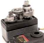
- Metal Gears - Metal gears have been around for sometime now. Although the heaviest and having the highest wear rate of all gear types, they offer incredible strength. With a metal output shaft, side-loads can be much greater. In applications that are jarred around, metal gears are best. Unfortunately, due to wear, metal gears will eventually develop slight play in the gear-train. Accuracy will slowly be lost.
- Titanium Gears - Titanium gears are simply awesome. Virtually no wear after years of use and 48 times stronger than Nylon gears. If your application is critical and you can not afford a gear failure, Titanium is the way to go.
Driving DC Motors or Other Loads from a RC Signal
You can go a few ways to control loads such as motors from an RC controller. Below are some methods
Method 1 You can use this RC switch to turn a load on and off. You will not be able to remotely control the direction. This is ideal for turning a light on and off or turning a motor on and off that only operates in one direction. The Relay acts like a switch, so any voltage (up to 240VAC) can be used. The contact are rated for 10Amps. The relay is triggered by a on-board microcontroller that monitors the pulse width of the receiver channel.
Method 2 You can just use this RC switch to drive a motor fwd/off/and reverse if you don't need speed control. The RC switch has limit switch inputs to limit motion in either or both directions. The relay acts like a switch, so any voltage (up to 240VAC) can be used. The relay contacts are rated for 8 Amps. The relay is triggered by a on-board microcontroller that monitors the pulse width of the receiver channel. When the stick is pushed one direction, just the single pole relay comes on driving the load forward, then the stick is pushed the other direction, both the single pole and double pole relay are pulled in turning the load on and reversing it.
Method 3 If you want speed control on your motor, you can use a Pulse Width Modulation (PWM) motor controller with Autonomous Robot Kitsour RC interface board. Pulse-width modulation: A technique used in DC-DC switching regulators where the duty cycle of the clock driving the main power switch is varied with the load in order to maintain output voltage. The technique is used in DC motor-control applications to vary motor RPM.
A microcontroller needs to read and measure the pulse width of the RC receiver. It then needs to covert that to a PWM Duty cycle to drive a PWM motor controller. The image on the right shows the PWM output compared to RC input for one channel. The microcontroller reads two RC channels and gives you 2 PWM outputs. The microcontroller PWM output can be set on as two independent controls or the channels can be mixed. In addition to the PWM output, each PWM has a direction bit so when the stick is in reverse the direction bit is high, when the stick is pushed forward the direction bit is low.
The microcontroller should be been programmed to filter and dismiss most erratic or lost readings.
The PWM signals that are output from the microcontroller are only TTL levels (5V Transistor Transistor Logic). To drive a motor or other load you need to take the PWM TTL signal and amplify it. Our PWMs are rated for 3Amps and operate in 12-55VDC, which is good for the IG32 or IG42 motors. The PWMs can be run in parallel, i.e. 2 PWMS motor controllers driven off of one PWM microcontroller output. i.e. with our ATR kits, we run two PWM to the left 2 motors (one per motor) and then two PWMs to the right motors when using the larger IG42 motors.
Method 4
You can use an integrated Sabertooth 2x5, Sabertooth 2x12, Sabertooth 2x25, Sabertooth 2x32, or Sabertooth 2x60 motor controller. Both motor controllers have an RC mode. Both Motor controllers are dual channel, so they can be used to mix you radio signals for single stick skid steering or they can operate independently. These controllers works great and are easy to hook up and get running. These controllers also supply 5V to drive your receiver. The 5V supply is 1A switching supply, so it should only be used for the receiver with no additional loads such as heavy duty servos plugged into the receiver (you will want to use a separate 5V supply if you want to add heavy duty servos or many light duty servos (can draw max of 850mA since the receiver will sometimes draw 150mA) to the other channels of the receiver. We also carry the Syren 10, 25, 50 motor controllers for those who only want to drive one motor and save a little money from the dual motor controllers.
- Sabertooth 2x5
- Sabertooth 2x12
- Sabertooth 2x25
- Sabertooth 2x32
- Sabertooth 2x60
- Syren 10A Motor Controller
- Syren 25A Motor Controller
- Syren 50A Motor Controller
Motor Hookup
In all cases, you want to hook up your motors properly using our electric motor hookup kit.
RC Controllers and Receivers
RC controllers can be found on the link below. All of the above will work with any RC controller. PCM radios like the Optic6 and Eclipse7 have better range and reliability since these are digital radios and can be programmed with fail safes.
We offer a variety of transmitters and receivers that get great range and reliability regardless of the other 2.4GHz systems around like routers and phones. The other benefit of 2.4GHz is most motor noise and mechanical noise/interference is well below this frequency which often causes issues with the 72 and 75MHz radio systems. We have many different types of receivers, each having their own pros and cons. Two of the biggest features you want to think about with a RC receiver are how many channels you will need and how the robot will respond in case of RC disconnect.
The amount of channels required depends on the functionality of the robot. A robot that only needs to drive will need two channels for drive forward and turn, while one that also has a pan/tilt/Zoom camera will need 5. You can see how this will quickly increase as the functionality increases. We have receivers that have as high as 9 channels or as low as 4.
The second thing you need to consider is how the robot should respond in case of RC disconnect. This can happen for many different reasons and is more likely then you would expect. Your robot could get out of range of the controller, your controller may run out of battery, something could cause interference between the controller and the robot or anything else that would stop communication to the robot and the controller. Receivers come with failsafe options. Failsafe's are a pre-set state that the robot will go into when they lose connection, however if the failsafe is turned off it will keep the last action they were commanded to. It is recommended that these need to be turned on before using a robot.
Having a default state for a robot to return to in case of loss of communication is extremely important. One example of this would be, think about a robot that is designed to drive very fast. While driving it away from yourself, you get out of range of the robot.The robot losses connection and you do not have a failsafe receiver your robot will keep driving away from you until you catch it(assuming you can) and turn it off or it runs out of battery. This can be very dangerous for the robot as a loss in control could lead to it running head on into a wall or worse traffic. With the failsafe state set, the robot could be told to shut off the motors. You could then take a few steps and tell the robot to turn around and come back, instead of chasing it down the road. Another interesting application of the failsafe receivers is you can set it to any state you would like rather then just everything off. Say you are flying a plane in the night equipt with lights. If your remote's batteries die, you could set the state of your plays to be half speed flying in circles with the lights on. This allows the robot to not drop out of the sky and the lights make it easier to find. Here is a list of our receivers.
Receivers
- FlySky FS-i6 2.4G 6CH Transmitter & Receiver
- FlySky FS-i6X 2.4G 10CH Transmitter & Receiver
- FlySky FS-i6s 2.4G 10CH Transmitter & Receiver
- Spektrum AR6110e DSM2 ML 6CH Fail Safe Receiver
- Spektrum Remote Receiver Extension - 36 inch
Binding
Receiver and transmitters when bought together are bound together. If the transmitter gets broke in use then you can bind a new transmitter to the existing receiver. Follow these steps:
- Turn off both the receiver and controller
- Plug the binding plugs(included with purchase) into the "bind" slot of the receiver
- Turn on the receiver, there should be a fast blinking light, this signals waiting for binding
- Hold the binding button or switch on your controller
- Turn on the controller
- The controller will say "RX binding"
- Once the message is gone it should be ready use
- Check for connection
- Remove binding plug
- Restart both and check for connection still
Now you should set your failsafe state, this is done almost identically.
- Turn on both the receiver and controller
- Hold down OK button to enter menu
- Go to System Setup
- Go to RX Setup
- Go to Failsafe
- Select channel you want to turn the failsafe on, click ok, turn on to save hold down cancel
- Once the channels have failsafes saved hold down cancel to save and close the menu
The easiest/safest way to check your failsafe bind was successful, is to set the robot on blocks so the tracks/tires are off of the ground. Then turn on the robot and controller. Drive the robot and while the tracks/tires are spinning turn off the controller. The robot should stop moving. If the robot continues to move the failsafes did not save. If it does stop then the failsafes are saved and the robot is ready for use.


