Difference between revisions of "Motor Controller Support"
(Tag: Visual edit) |
(Tag: Visual edit) |
||
| (9 intermediate revisions by 5 users not shown) | |||
| Line 1: | Line 1: | ||
| − | + | Generally motors are wired to a motor controller to provide speed control to motors. The motor controller can be used to change the directions of the motor as well. If running motors in parallel (as in a 4WD the two left and the two right motors will be running together in parallel) you can wire them in parallel too. | |
| + | |||
| + | Motor Controllers take signals from a microprocessor or radio control receiver and convert it into a high current varying voltage. Motor controllers are rated based on the voltage and current requirements. You can take a look at some of our robot kits to get an idea of what size motor controller you will need. We carry RoboteQ motor controllers, which will take encoder inputs for speed and/or position control, as well as Dimension Engineering's Sabertooth with a Kangaroo for encoder input. | ||
| − | |||
A motor controller takes a low current low voltage input signal and drives a motor with higher voltages and currents. The input signal can be serial, I2C, RC input, PWM, etc. Listed below are the many types of motor controllers with a brief explanation of each one. For full details of each motor controller go to the item page. Each motor controller item page has supporting links to data sheets, manuals, etc. | A motor controller takes a low current low voltage input signal and drives a motor with higher voltages and currents. The input signal can be serial, I2C, RC input, PWM, etc. Listed below are the many types of motor controllers with a brief explanation of each one. For full details of each motor controller go to the item page. Each motor controller item page has supporting links to data sheets, manuals, etc. | ||
| − | + | ==How a Motor Controller Works== | |
| − | |||
| − | |||
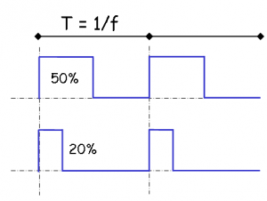
The output of a motor controller is PWM based, which stands for pulse width modulation. The concept of a PWM signal is to switch the output power on and off really fast in order to reduce the average voltage supplied to the motor in order to precisely control the speed of a motor. | The output of a motor controller is PWM based, which stands for pulse width modulation. The concept of a PWM signal is to switch the output power on and off really fast in order to reduce the average voltage supplied to the motor in order to precisely control the speed of a motor. | ||
| − | + | [[File:pulse-width-modulation.png|thumb|center|PWM Signal]] | |
| − | |||
| − | |||
| − | |||
| − | |||
==Motor Controller Comparison Table== | ==Motor Controller Comparison Table== | ||
| Line 272: | Line 267: | ||
==Available Motor Controllers== | ==Available Motor Controllers== | ||
Below is a grouped listing of various available motor controllers grouped by company. | Below is a grouped listing of various available motor controllers grouped by company. | ||
| − | |||
| − | |||
| − | |||
| − | |||
| − | |||
| − | |||
| − | |||
| − | |||
| − | |||
| − | |||
| − | |||
| − | |||
| − | |||
| − | |||
| − | |||
| − | |||
| − | |||
| − | |||
| − | |||
| − | |||
| − | |||
| − | |||
| − | |||
| − | |||
| − | |||
| − | |||
| − | |||
| − | |||
===Dimension Engineering=== | ===Dimension Engineering=== | ||
| Line 338: | Line 305: | ||
'''Size:''' 2.6 x 3.2 x .8 in (65mm x 80mm x 20mm) | '''Size:''' 2.6 x 3.2 x .8 in (65mm x 80mm x 20mm) | ||
| + | [[File:1616696070941.jpg|thumb]] | ||
| + | |||
====<sdr item id=1822>Sabertooth 2x32</sdr item>==== | ====<sdr item id=1822>Sabertooth 2x32</sdr item>==== | ||
'''Capacity and Voltage:''' Channels: 2 Voltage: 6-30V (33.6V max) Current: 32A continuous, 64A peak | '''Capacity and Voltage:''' Channels: 2 Voltage: 6-30V (33.6V max) Current: 32A continuous, 64A peak | ||
| Line 369: | Line 338: | ||
<br /> | <br /> | ||
| + | [[File:TE-098-125 tn.jpg|thumb]] | ||
====<sdr item id=848>SyRen 1x25</sdr item>==== | ====<sdr item id=848>SyRen 1x25</sdr item>==== | ||
| Line 376: | Line 346: | ||
'''Size:''' 2.4 x 2.3 x .8 in (61mm x 58mm x 21mm) | '''Size:''' 2.4 x 2.3 x .8 in (61mm x 58mm x 21mm) | ||
| + | |||
| + | |||
| + | [[File:1616693041031.jpg|thumb]] | ||
====<sdr item id=1197>SyRen 1x50</sdr item>==== | ====<sdr item id=1197>SyRen 1x50</sdr item>==== | ||
| Line 387: | Line 360: | ||
Multiple operating modes configurable via an on board DIP switch. | Multiple operating modes configurable via an on board DIP switch. | ||
| + | |||
===Pololu=== | ===Pololu=== | ||
| + | [[File:1616693108359.jpg|thumb]] | ||
====<sdr item id=1297>Dual MC33926 Motor Driver Shield for Arduino</sdr item>==== | ====<sdr item id=1297>Dual MC33926 Motor Driver Shield for Arduino</sdr item>==== | ||
| Line 398: | Line 373: | ||
'''Other Features:''' Simple motor control through an Arduino with the use of supplied libraries located [https://github.com/pololu/dual-mc33926-motor-shield here]. | '''Other Features:''' Simple motor control through an Arduino with the use of supplied libraries located [https://github.com/pololu/dual-mc33926-motor-shield here]. | ||
| + | [[File:1616693238420.jpg|thumb]] | ||
====<sdr item id=1296>Dual VNH5019 Motor Driver Shield for Arduino</sdr item>==== | ====<sdr item id=1296>Dual VNH5019 Motor Driver Shield for Arduino</sdr item>==== | ||
| Line 409: | Line 385: | ||
Not recommended for use with 24v batteries. | Not recommended for use with 24v batteries. | ||
| + | [[File:1616693399706.jpg|thumb]] | ||
====<sdr item id=1368>Pololu DRV8833 Dual Motor Driver Carrier</sdr item>==== | ====<sdr item id=1368>Pololu DRV8833 Dual Motor Driver Carrier</sdr item>==== | ||
| Line 416: | Line 393: | ||
'''Size:''' 0.5 x 0.8 in (12.7mm x 20.32mm) | '''Size:''' 0.5 x 0.8 in (12.7mm x 20.32mm) | ||
| + | |||
===RoboteQ=== | ===RoboteQ=== | ||
| + | [[File:1616694661327.jpg|thumb|141x141px]] | ||
====<sdr item id=1826>RoboteQ SDC2160 - 2x20A 60V Motor Controller with Encoder Input</sdr item>==== | ====<sdr item id=1826>RoboteQ SDC2160 - 2x20A 60V Motor Controller with Encoder Input</sdr item>==== | ||
| Line 427: | Line 406: | ||
'''Other Features:''' Forward & Reverse Speed Control. Separate or Mixed. Encoder Input for Speed and Position Control. | '''Other Features:''' Forward & Reverse Speed Control. Separate or Mixed. Encoder Input for Speed and Position Control. | ||
| + | [[File:1616694911002.jpg|thumb|146x146px]] | ||
====<sdr item id=1834>RoboteQ MDC2460 - 2x60A 60V Motor Controller with Encoder Input</sdr item>==== | ====<sdr item id=1834>RoboteQ MDC2460 - 2x60A 60V Motor Controller with Encoder Input</sdr item>==== | ||
| Line 436: | Line 416: | ||
'''Other Features:''' Forward & Reverse Speed Control. Separate or Mixed. Encoder Input for Speed and Position Control. | '''Other Features:''' Forward & Reverse Speed Control. Separate or Mixed. Encoder Input for Speed and Position Control. | ||
| + | [[File:1616695950978.jpg|thumb|146x146px]] | ||
====<sdr item id=2233>RoboteQ XDC2460 - 2x150A 60V Motor Controller with Encoder Input</sdr item>==== | ====<sdr item id=2233>RoboteQ XDC2460 - 2x150A 60V Motor Controller with Encoder Input</sdr item>==== | ||
| Line 445: | Line 426: | ||
'''Other Features:''' Forward & Reverse Speed Control. Separate or Mixed. Encoder Input for Speed and Position Control. | '''Other Features:''' Forward & Reverse Speed Control. Separate or Mixed. Encoder Input for Speed and Position Control. | ||
| + | |||
===RoboClaw=== | ===RoboClaw=== | ||
| + | [[File:1616693948013.jpg|thumb]] | ||
| + | |||
====<sdr item id=2626>RoboClaw 2x7A Motor Controller</sdr item>==== | ====<sdr item id=2626>RoboClaw 2x7A Motor Controller</sdr item>==== | ||
'''Capacity and Voltage:''' Channels: 2 Max Voltage: 6-34V Current: 7.5A continuous, 15A peak per channel | '''Capacity and Voltage:''' Channels: 2 Max Voltage: 6-34V Current: 7.5A continuous, 15A peak per channel | ||
| Line 455: | Line 439: | ||
'''Other Features:''' Built-in commands for controlling acceleration, deceleration, distance, speed, current sense, voltage limits and more. | '''Other Features:''' Built-in commands for controlling acceleration, deceleration, distance, speed, current sense, voltage limits and more. | ||
| + | [[File:1616693979267.jpg|thumb]] | ||
| + | |||
====<sdr item id=2627>RoboClaw 2x15A Motor Controller</sdr item>==== | ====<sdr item id=2627>RoboClaw 2x15A Motor Controller</sdr item>==== | ||
'''Capacity and Voltage:''' Channels: 2 Max Voltage: 6-34V Current: 15A continuous, 30A peak per channel | '''Capacity and Voltage:''' Channels: 2 Max Voltage: 6-34V Current: 15A continuous, 30A peak per channel | ||
| Line 463: | Line 449: | ||
'''Other Features:''' Built-in commands for controlling acceleration, deceleration, distance, speed, current sense, voltage limits and more. | '''Other Features:''' Built-in commands for controlling acceleration, deceleration, distance, speed, current sense, voltage limits and more. | ||
| + | [[File:1616694018962.jpg|thumb]] | ||
| + | |||
====<sdr item id=2629>RoboClaw 2x30A Motor Controller</sdr item>==== | ====<sdr item id=2629>RoboClaw 2x30A Motor Controller</sdr item>==== | ||
'''Capacity and Voltage:''' Channels: 2 Max Voltage: 6-34V Current: 30A continuous, 60A peak per channel | '''Capacity and Voltage:''' Channels: 2 Max Voltage: 6-34V Current: 30A continuous, 60A peak per channel | ||
| Line 471: | Line 459: | ||
'''Other Features:''' Built-in commands for controlling acceleration, deceleration, distance, speed, current sense, voltage limits and more. | '''Other Features:''' Built-in commands for controlling acceleration, deceleration, distance, speed, current sense, voltage limits and more. | ||
| + | [[File:1616694051739.jpg|thumb]] | ||
| + | |||
====<sdr item id=2630>RoboClaw 2x60A Motor Controller</sdr item>==== | ====<sdr item id=2630>RoboClaw 2x60A Motor Controller</sdr item>==== | ||
'''Capacity and Voltage:''' Channels: 2 Max Voltage: 6-34V Current: 60A continuous, 120A peak per channel | '''Capacity and Voltage:''' Channels: 2 Max Voltage: 6-34V Current: 60A continuous, 120A peak per channel | ||
| Line 479: | Line 469: | ||
'''Other Features:''' Built-in commands for controlling acceleration, deceleration, distance, speed, current sense, voltage limits and more. | '''Other Features:''' Built-in commands for controlling acceleration, deceleration, distance, speed, current sense, voltage limits and more. | ||
| + | [[File:1616694089174.jpg|thumb]] | ||
====<sdr item id=2628>RoboClaw Solo 30A Motor Controller</sdr item>==== | ====<sdr item id=2628>RoboClaw Solo 30A Motor Controller</sdr item>==== | ||
| Line 488: | Line 479: | ||
'''Other Features:''' Built-in commands for controlling acceleration, deceleration, distance, speed, current sense, voltage limits and more. | '''Other Features:''' Built-in commands for controlling acceleration, deceleration, distance, speed, current sense, voltage limits and more. | ||
| − | |||
| − | |||
| − | + | <br /> | |
| − | + | ===SuperDroid Robots=== | |
| − | + | [[File:TE-294-001-F.jpg|thumb|link=https://wiki.sdrobots.com/index.php/File:TE-294-001-F.jpg]] | |
| − | + | ====<sdr item id=2316>PWM Motor Controller 30A 5.5-36V</sdr item>==== | |
| − | + | '''Capacity and Voltage:''' Channels: 1 Voltage: 5.5-36VDC Current: 30 Amp | |
| − | |||
| − | |||
| − | + | '''Control Inputs:''' PWM input (a simulated 0-5V output from a microcontroller). Also needs input for direction (INA, INB) | |
| − | |||
| − | + | '''Size:''' 1.25 x 2.5 in (31.75mm x 63.5mm) | |
| − | |||
| − | + | '''Other Features:''' ENA and ENB have pull up resistors on them so you do not have to hook up IO to them if you don't wish to use them. | |
| − | |||
| − | == | + | We offer hookup kits for these: PWM to PIC Hookup Kit. |
| − | + | ==Schematics== | |
| + | Below are some schematics that may not apply directly to what you wish to do, but will give you a starting point or you can use pieces of it. | ||
| − | + | *[https://wiki.sdrobots.com/index.php/Electrical_Schematics Electrical Schematics] | |
| − | == | + | ==Common Questions (FAQ):== |
| − | + | Question: A very common question that we get is "how do I hook up four motors to a two-channel motor controller?" Most of our 4WD robots use four motors (one motor per wheel). | |
| − | + | Answer: Since the left motors need to act together as do the right motors, the solution is very easy. Just parallel the left motors to one channel of the motor controller, and parallel the right motors to the second channel. The same goes for 6WD robots. Just make sure the sum of the stall torque for each motor does not exceed the motor controller rating. (ie: 2 motors with 15A stall will exceed the rating of a 25A controller in a stall condition. | |
| + | [[Category:Electrical Components]] | ||
| − | + | [[Category:How to Build a Robot]] | |
| − | |||
| − | |||
| − | |||
| − | |||
| − | [[Category: | ||
Latest revision as of 20:26, 14 April 2021
Generally motors are wired to a motor controller to provide speed control to motors. The motor controller can be used to change the directions of the motor as well. If running motors in parallel (as in a 4WD the two left and the two right motors will be running together in parallel) you can wire them in parallel too.
Motor Controllers take signals from a microprocessor or radio control receiver and convert it into a high current varying voltage. Motor controllers are rated based on the voltage and current requirements. You can take a look at some of our robot kits to get an idea of what size motor controller you will need. We carry RoboteQ motor controllers, which will take encoder inputs for speed and/or position control, as well as Dimension Engineering's Sabertooth with a Kangaroo for encoder input.
A motor controller takes a low current low voltage input signal and drives a motor with higher voltages and currents. The input signal can be serial, I2C, RC input, PWM, etc. Listed below are the many types of motor controllers with a brief explanation of each one. For full details of each motor controller go to the item page. Each motor controller item page has supporting links to data sheets, manuals, etc.
Contents
How a Motor Controller Works
The output of a motor controller is PWM based, which stands for pulse width modulation. The concept of a PWM signal is to switch the output power on and off really fast in order to reduce the average voltage supplied to the motor in order to precisely control the speed of a motor.
Motor Controller Comparison Table
| Electrical Specs: Voltage and Current | Control Inputs | ||||||||||
|---|---|---|---|---|---|---|---|---|---|---|---|
| Motor Controller | Channels | Min Voltage (VDC) | Max Voltage (VDC) | Continuous Current per Motor (A) | Peak Current per Motor (A) | Analog | RC | Serial | Encoders | Closed Loop Speed Control | Size (in x in x in) |
| Sabertooth 2x5 | 2 | 6 | 18 | 5 | 10 | Y | Y | Y | N | N | 1.8x1.6x0.5 |
| Sabertooth 2x12 | 2 | 6 | 24 | 12 | 25 | Y | Y | Y | N | N | 3.0x2.3x0.7 |
| Sabertooth 2x12 RC | 2 | 6 | 24 | 12 | 25 | N | Y | N | N | N | 3.0x2.3x0.7 |
| Sabertooth 2x25 | 2 | 6 | 24 | 25 | 50 | Y | Y | Y | N | N | 3.2x2.6x0.8 |
| Sabertooth 2x32 |
2 | 6 | 30 | 32 | 64 | Y | Y | Y | N | N | 3.5x2.75x1.0 |
| Sabertooth 2x60 |
2 | 6 | 30 | 60 | 120 | Y | Y | Y | N | N | 3.5x3.0x1.8 |
| Syren 1x10 |
1 | 6 | 24 | 10 | 15 | Y | Y | Y | N | N | 2.25x1.4x0.6 |
| Syren 1x25 |
1 | 6 | 24 | 25 | 45 | Y |
Y |
Y |
N |
N |
2.4x2.3x0.8 |
| Syren 1x50 |
1 | 6 | 30 | 50 | 100 | Y |
Y |
Y |
N |
N |
3.5x3.0x1.3 |
| RoboteQ SDC2160 2x20A |
2 | 10 | 60 | 10 | 20 | Y | Y | Y | Y | Y | 2.75x2.75x0.80 |
| RoboteQ MDC2460 2x60A |
2 | 10 | 60 | 50 | 60 | Y | Y | Y | Y | Y | 5.5x5.5x1.0 |
| RoboteQ XDC2460 2x150A |
2 | 10 | 60 | 80 | 150 | Y | Y | Y | Y | Y | 9.0x5.5x1.6 |
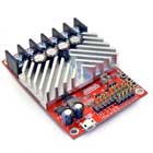
| RoboClaw 2x7A |
2 | 6 | 34 | 7.5 | 15 | Y | Y | Y | Y | Y | 1.65x1.9x0.67 |
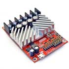
| RoboClaw 2x15A |
2 | 6 | 34 | 15 | 30 | Y | Y | Y | Y | Y | 2.91x2.05x0.67 |
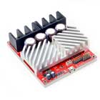
| RoboClaw 2x30A |
2 | 6 | 34 | 30 | 60 | Y | Y | Y | Y | Y | 2.91x2.05x0.67 |
| RoboClaw 2x60A |
2 | 6 | 34 | 60 | 120 | Y | Y | Y | Y | Y | 3.94x3.38x0.98 |
| RoboClaw Solo 30A |
1 | 6 | 34 | 30 | 60 | Y | Y | Y | Y | Y | 2.36x1.28x0.91 |
Available Motor Controllers
Below is a grouped listing of various available motor controllers grouped by company.
Dimension Engineering
Sabertooth 2x5
Capacity and Voltage: Channels: 2 Voltage: 6-18VDC Current: 5A continuous, 10A peak per channel
Control Inputs: Analog voltage, radio control, serial and packetized serial. Sabertooth has independent and speed + direction operating modes, making it the ideal driver for differential drive (tank style) robots and more.
Size: 1.8 x 1.6 x .5 in (45mm x 40mm x 13mm)
Sabertooth 2x12 RC
Capacity and Voltage: Channels: 2 Voltage: 6-24VDC Current: 12A continuous, 25A peak per motor
Control Inputs: Radio control only. Sabertooth has independent and speed + direction operating modes, making it the ideal driver for differential drive (tank style) robots and more.
Size: 2.3 x 3 x .7 in (59mm x 75mm x 17mm)
Other Features: This motor controller has a 1 Amp Switching BEC, which is very useful power the 2.4GHz receivers (that draw about 130mA during sync).
Sabertooth 2x12
Capacity and Voltage: Channels: 2 Voltage: 6-24 VDC Current: 12A continuous, 25A peak per motor
Control Inputs: Analog voltage, radio control, serial and packetized serial. Sabertooth has independent and speed + direction operating modes, making it the ideal driver for differential drive (tank style) robots and more.
Size: 2.3 x 3 x .7 in (59mm x 75mm x 17mm)
Other Features: This motor controller has a 1 Amp Switching BEC, which is very useful power the 2.4GHz receivers (that draw about 130mA during sync).
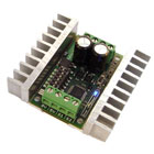
Sabertooth 2x25
Capacity and Voltage: Channels: 2 Operating Voltage: 6-24VDC Current: 25A continuous, 50A peak per channel
Control Inputs: Analog voltage, radio control, serial and packetized serial. Sabertooth has independent and speed + direction operating modes, making it the ideal driver for differential drive (tank style) robots and more.
Size: 2.6 x 3.2 x .8 in (65mm x 80mm x 20mm)
Sabertooth 2x32
Capacity and Voltage: Channels: 2 Voltage: 6-30V (33.6V max) Current: 32A continuous, 64A peak
Control Inputs: Analog voltage, radio control, serial and packetized serial.
Size: 2.75 x 3.5 x 1.0 in (70mm x 90mm x 25mm)
Other Features: Multiple operating modes configurable via an on board DIP switch.
Easy speed/direction control for pumps, conveyors and automation.
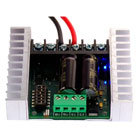
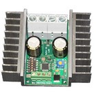
Sabertooth Dual 60A
Capacity and Voltage: Channels: 2 Voltage: 6-30V (33.6V max) Current: 60A continuous, 120A peak per channel
Control Inputs: Analog voltage, radio control, serial and packetized serial. Sabertooth has independent and speed + direction operating modes, making it the ideal driver for differential drive (tank style) robots and more.
Size: 3.0 x 3.5 x 1.8 in (76mm x 89mm x 46mm)
Other Features: This motor controller has a 1 Amp Switching BEC, which is very useful power the 2.4GHz receivers (that draw about 130mA during sync). Thermal and overcurrent protection and Lithium protection mode.
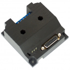
SyRen 1x10
Capacity and Voltage: Channels: 1 Voltage: 12-24VDC (30V max) Current: 10A continuous, 15A peak
Control Inputs: Analog voltage, radio control, serial and packetized serial.
Size: 1.4 x 2.25 x .6 in (35mm x 57mm x 14mm)
SyRen 1x25
Capacity and Voltage: Channels: 1 Voltage: 12-24VDC (30V max) Current: 25A continuous, 45A peak
Control Inputs: Analog voltage, radio control, serial and packetized serial.
Size: 2.4 x 2.3 x .8 in (61mm x 58mm x 21mm)
SyRen 1x50
Capacity and Voltage: Channels: 1 Voltage: 6-30V (33.6V max) Current: 50A continuous, 100A peak
Control Inputs: Analog voltage, radio control, serial and packetized serial.
Size: 3.0 x 3.5 x 1.3 in (76.5mm x 89mm x 33mm)
Other Features: Multiple operating modes configurable via an on board DIP switch.
Multiple operating modes configurable via an on board DIP switch.
Pololu
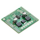
Dual MC33926 Motor Driver Shield for Arduino
Capacity and Voltage: Channels: 2 Voltage: 5-28V Current: 3A continuous, 5A max per channel
Control Inputs: Arduino pins 4, 7, 8, 9, 10 and 12
Size: Arduino compatible
Other Features: Simple motor control through an Arduino with the use of supplied libraries located here.
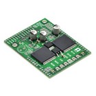
Dual VNH5019 Motor Driver Shield for Arduino
Capacity and Voltage: Channels: 2 Voltage: 5.5-24V Current: 12A continuous, 30A peak per channel
Control Inputs: Arduino pins 4, 7, 8, 9, 10 and 12
Size: Arduino compatible
Other Features: Simple motor control through an Arduino with the use of supplied libraries located here.
Not recommended for use with 24v batteries.
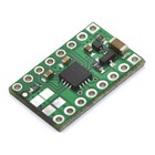
Pololu DRV8833 Dual Motor Driver Carrier
Capacity and Voltage: Channels: 2 Voltage: 2.7-10.8V Current: 1.2A continuous, 2A peak per channel
Control Inputs: PWM and Digital Inputs. See datasheet for details.
Size: 0.5 x 0.8 in (12.7mm x 20.32mm)
RoboteQ
RoboteQ SDC2160 - 2x20A 60V Motor Controller with Encoder Input
Capacity and Voltage: Channels: 2 Voltage: 10-60V Current: 10A continuous, 20A peak per channel
Control Inputs: Radio Control Input, Serial Input, Analog Input
Size: 2.6 x 2.6 x 0.75 in (66mm x 66mm x 19mm)
Other Features: Forward & Reverse Speed Control. Separate or Mixed. Encoder Input for Speed and Position Control.
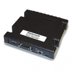
RoboteQ MDC2460 - 2x60A 60V Motor Controller with Encoder Input
Capacity and Voltage: Channels: 2 Max Voltage: 10-60V Current: 50A continuous, 60A peak per channel
Control Inputs: Radio Control Input, Serial Input, Analog Input
Size: 5.5 x 5.5 x 1 in (139.7mm x 139.7mm x 25.4mm)
Other Features: Forward & Reverse Speed Control. Separate or Mixed. Encoder Input for Speed and Position Control.
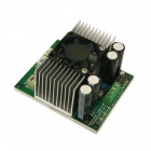
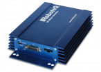
RoboteQ XDC2460 - 2x150A 60V Motor Controller with Encoder Input
Capacity and Voltage: Channels: 2 Max Voltage: 10-60V Current: 80A continuous, 150A peak per channel
Control Inputs: Radio Control Input, Serial Input, Analog Input
Size: 9 x 5.5 x 1.6in (228.6mm x 139.7mm x 40.6mm)
Other Features: Forward & Reverse Speed Control. Separate or Mixed. Encoder Input for Speed and Position Control.
RoboClaw
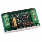
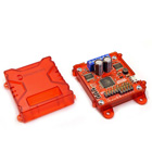
RoboClaw 2x7A Motor Controller
Capacity and Voltage: Channels: 2 Max Voltage: 6-34V Current: 7.5A continuous, 15A peak per channel
Control Inputs: Radio Control Input, Serial Input, Analog Input, USB, Position Control, Velocity Control
Size: 1.9 x 1.7 x 0.7in (48mm x 42mm x 17mm)
Other Features: Built-in commands for controlling acceleration, deceleration, distance, speed, current sense, voltage limits and more.
RoboClaw 2x15A Motor Controller
Capacity and Voltage: Channels: 2 Max Voltage: 6-34V Current: 15A continuous, 30A peak per channel
Control Inputs: Radio Control Input, Serial Input, Analog Input, USB, Position Control, Velocity Control
Size: 2.9 x 2 x 0.7in (74mm x 52mm x 17mm)
Other Features: Built-in commands for controlling acceleration, deceleration, distance, speed, current sense, voltage limits and more.
RoboClaw 2x30A Motor Controller
Capacity and Voltage: Channels: 2 Max Voltage: 6-34V Current: 30A continuous, 60A peak per channel
Control Inputs: Radio Control Input, Serial Input, Analog Input, USB, Position Control, Velocity Control
Size: 2.9 x 2 x 0.7in (74mm x 52mm x 17mm)
Other Features: Built-in commands for controlling acceleration, deceleration, distance, speed, current sense, voltage limits and more.
RoboClaw 2x60A Motor Controller
Capacity and Voltage: Channels: 2 Max Voltage: 6-34V Current: 60A continuous, 120A peak per channel
Control Inputs: RC Input, Serial Input, Analog Input, USB, Position Control, Velocity Control
Size: 3.9 x 3.4 x 1in (100mm x 86mm x 25.4mm)
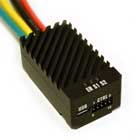
Other Features: Built-in commands for controlling acceleration, deceleration, distance, speed, current sense, voltage limits and more.
RoboClaw Solo 30A Motor Controller
Capacity and Voltage: Channels: 1 Max Voltage: 6-34V Current: 30A continuous, 60A peak
Control Inputs: Radio Control Input, Serial Input, Analog Input, USB, Position Control, Velocity Control
Size: 2.4 x 1.3 x 0.9in (60mm x 32.5mm x 23mm)
Other Features: Built-in commands for controlling acceleration, deceleration, distance, speed, current sense, voltage limits and more.
SuperDroid Robots
PWM Motor Controller 30A 5.5-36V
Capacity and Voltage: Channels: 1 Voltage: 5.5-36VDC Current: 30 Amp
Control Inputs: PWM input (a simulated 0-5V output from a microcontroller). Also needs input for direction (INA, INB)
Size: 1.25 x 2.5 in (31.75mm x 63.5mm)
Other Features: ENA and ENB have pull up resistors on them so you do not have to hook up IO to them if you don't wish to use them.
We offer hookup kits for these: PWM to PIC Hookup Kit.
Schematics
Below are some schematics that may not apply directly to what you wish to do, but will give you a starting point or you can use pieces of it.
Common Questions (FAQ):
Question: A very common question that we get is "how do I hook up four motors to a two-channel motor controller?" Most of our 4WD robots use four motors (one motor per wheel).
Answer: Since the left motors need to act together as do the right motors, the solution is very easy. Just parallel the left motors to one channel of the motor controller, and parallel the right motors to the second channel. The same goes for 6WD robots. Just make sure the sum of the stall torque for each motor does not exceed the motor controller rating. (ie: 2 motors with 15A stall will exceed the rating of a 25A controller in a stall condition.
