Difference between revisions of "Sensor Selection"
(Tag: Visual edit) |
|||
| (45 intermediate revisions by the same user not shown) | |||
| Line 1: | Line 1: | ||
| − | This is a practical guide to selecting sensors for your project. For each sensor there is a breakdown of what physical parameters the sensor is measuring, the conditions the sensor works best in, and some things the sensor does well and poorly. | + | This is a practical guide to selecting [[:Category:Sensors|sensors]] for your project. For each sensor there is a breakdown of what physical parameters the sensor is measuring, the conditions the sensor works best in, and some things the sensor does well and poorly. |
| − | == Positioning System Sensors == | + | ==[[Positioning System]] Sensors== |
| − | These sensors are used to generate estimates of the robot’s position state (position, orientation/heading, speed, and/or acceleration). | + | These sensors are used as part of a [[Positioning_System|positioning system]] to generate estimates of the robot’s position state (position, orientation/heading, speed, and/or acceleration). |
| − | === Wheel Encoders === | + | ===[[Encoders|Wheel Encoders]]=== |
| + | [[File:us digital h1 encoder.jpg|thumb|250x250px|US Digital H1 Encoder]] | ||
| + | Rotary [[Wheel_Encoders|encoders]] are devices that generate electrical pulses as they rotate. The angle or rate of rotation that the encoder is experiencing can be measured by monitoring the number or frequency of the pulses. In robotics, encoders are commonly attached to the robot's drive [[motors]] and used to measure the robot's linear speed, angular speed, and distance traveled. | ||
| − | + | '''Measurement:''' When attached to the drive motors, measures wheel speed. This information can then be used to track the robot’s linear and angular/rotational speed and subsequently the robot’s position and heading by integrating the data over time | |
| + | '''Ideal operating conditions:''' Robot operating on smooth/even ground where wheels maintain constant rolling contact with no slip. | ||
| − | + | '''Sensor Pros:''' | |
| − | |||
| − | |||
| − | |||
| − | |||
| − | |||
| − | |||
| − | |||
| − | |||
| − | |||
| − | |||
| − | |||
| − | |||
| − | + | *Quite accurate over short time periods/distances | |
| + | *Works indoors and outdoors, day or night | ||
| + | *Good for mitigating discrete jumps in position and orientation when fused with other sensors | ||
| + | *Great fallback sensor when things go wrong | ||
| + | *Can be used for closed loop speed control of the wheels | ||
| − | + | '''Sensor Cons:''' | |
| − | * | + | *Requires initial calibration between encoder counts and amount of robot movement |
| − | + | *Assumes no slip between robot wheel and ground. An unstable or inconsistent surface beneath the robot can lead to wheel slippage. Skid-steer robots also experience wheel slippage while turning. This causes error in the estimated robot position because the wheel moves but the robot doesn’t. | |
| − | * | + | *Position errors from wheel slippage and imperfect calibration accumulate over time/distance to give a progressively worse position estimate. When used to measure speed instead of position this is less of an issue. |
| − | + | *Additional electronics are often needed to keep track of the encoder counts. However, some motor controllers (such as Roboteq models) have this functionality built-in. | |
| − | |||
| − | * | ||
| − | |||
| − | |||
| − | |||
| − | * | ||
| − | |||
| − | |||
| − | |||
| − | |||
| − | === | + | ===[[Inertial_Measurement_Unit|Inertial Measurement Unit (IMU)]]=== |
| + | [[File:minimu-9 imu.jpg|alt=|thumb|250x250px|<sdr item id=2274>Pololu MinIMU-9 v5 IMU</sdr item>]] | ||
| + | The [[Inertial_Measurement_Unit|IMU]] is typically a combination of three sensors: accelerometer, gyroscope, and magnetometer. | ||
| − | === Marvelmind Indoor Positioning System (IPS) === | + | '''Measurement:''' Linear acceleration (accelerometer), angular velocity (gyroscope), heading (magnetometer/compass). 3D orientation (roll/pitch/yaw) when values are combined using sensor fusion techniques. |
| + | |||
| + | '''Ideal operating conditions:''' Can be used in nearly any conditions. Magnetometer needs to avoid EM noise and ferrous materials. | ||
| + | |||
| + | '''Sensor Pros:''' | ||
| + | |||
| + | *Can be used in nearly any conditions – indoor/outdoor, day/night, uneven surfaces. Requires few assumptions to use. This versatility makes the IMU a useful addition to any sensor setup. | ||
| + | *Good for mitigating discrete jumps in position and orientation measurement when fused with other sensors. | ||
| + | *Useful in both 2D and 3D applications. | ||
| + | *Produces a reasonable 3D orientation estimate. | ||
| + | *Acceleration measurements can be integrated to estimate velocity and position. However, these estimates are noisy and will accumulate error over time. Fusing the acceleration data with other sensors is a better approach. | ||
| + | *Very inexpensive. Decent IMUs are available for less than $20. | ||
| + | |||
| + | '''Sensor Cons:''' | ||
| + | |||
| + | *Requires initial calibration | ||
| + | *It is difficult to work directly with raw IMU data due mainly to noise. Filtering algorithms are needed to extract useful information. Higher end IMUs can filter the data before outputting it. | ||
| + | *Gyroscopes are susceptible to drift. | ||
| + | *Magnetometer/compass output is unreliable. Must be corrected based on where it is being used in the world. Even then the compass heading is inaccurate (+-20 degrees or worse). Also vulnerable to external magnetic sources. | ||
| + | |||
| + | ===[[GPS]]=== | ||
| + | [[File:here gps.jpg|thumb|Here GPS Receiver]] | ||
| + | '''Measurement:''' GPS receiver exchanges data with GPS satellite system to obtain time and location information anywhere on the planet. For basic GPS the position accuracy is about 10-20 meters. WAAS can reach an accuracy of under 3 meters and RTK can reach 1 cm. | ||
| + | |||
| + | '''Ideal operating conditions:''' Outdoors with an unobstructed view of the sky. Does not work indoors! WAAS only works in the US and requires a nearby public reference station to feed it correctional data. RTK requires sky visibility in a cone at an elevation of ~30 degrees to the horizon and a base station setup very close by for corrections. | ||
| + | |||
| + | '''Sensor Pros:''' | ||
| + | |||
| + | *Data is easily processed, allowing the use of cheaper [[Electronic_Control_Units|microcontrollers]] | ||
| + | *Can receive positioning data anywhere in the world (while outside) with no setup. This is a huge positive. | ||
| + | *WAAS and RTK can have decent accuracy with some extra setup | ||
| + | |||
| + | '''Sensor Cons:''' | ||
| + | |||
| + | *Slow update rate | ||
| + | *Only works outside | ||
| + | *Generally not accurate enough by itself to be used for robot navigation | ||
| + | *WAAS has reasonable accuracy but only works in the US | ||
| + | *While RTK has impressive accuracy, it is difficult to setup and get working reliably in real-time | ||
| + | *Difficult to align with map data | ||
| + | |||
| + | ===<sdr item id=2562>Marvelmind Indoor Positioning System (IPS)</sdr item>=== | ||
| + | [[File:Marvelmind IPS.jpg|thumb|250x250px|<sdr item id=2562>Marvelmind IPS Starter Kit</sdr item>]] | ||
This is a positioning system that uses a set of stationary ultrasonic beacons to track the position of a mobile beacon attached to the robot. | This is a positioning system that uses a set of stationary ultrasonic beacons to track the position of a mobile beacon attached to the robot. | ||
| − | + | '''Measurement:''' Position in 3D space. | |
| − | + | ||
| − | + | '''Ideal operating conditions:''' Can be used in nearly any conditions. | |
| − | + | ||
| − | + | '''Sensor Pros:''' | |
| − | + | ||
| − | + | *Directly provides accurate 3D position data (about 1-2” error) with no additional data processing required. This is a big deal since generating reliable position data is one of the main goals of the robot’s positioning system (you still need orientation though). | |
| − | + | *No computational load is required from the robot which allows the use of a less powerful [[Electronic Control Units|microcontroller]]. | |
| − | + | *Despite the name, can be used outdoors. | |
| − | + | ||
| − | + | '''Sensor Cons:''' | |
| + | |||
| + | *Setup required. Must place stationary beacons beforehand which limits portability of the robot. Marvelmind PC software and stationary beacon self-arrangement algorithm make it so setup isn’t too much of a hassle though. | ||
| + | *Beacons have batteries that must be recharged from time to time. | ||
| + | *Position is subject to discrete jumps. Fusion with encoder or imu measurements helps with this. | ||
| + | *Line of sight requirements are hard to meet in a cluttered environment. | ||
| + | *Susceptible to interference from other sources of ultrasonic noise. | ||
| + | |||
| + | ==Simple [[Obstacle Detection]] Sensors== | ||
| + | |||
| + | These sensors are able to [[Obstacle Detection|detect obstacles]] at a point, in a line, or in a small cone. Some may also be used as one-dimensional positioning sensors, e.g. to track the distance between the robot and a wall. | ||
| + | |||
| + | ===Contact/Bumper/Limit Switches=== | ||
| + | [[File:limit switch.jpg|thumb|250x250px|Contact Switch]] | ||
| + | '''Obstacle Detection:''' This is a simple switch that is positioned on the robot such that it is tripped when the robot hits an obstacle. Output is usually a simple high/low digital signal. | ||
| + | |||
| + | '''Ideal operating conditions:''' Can be used in any conditions. The only consideration is where to place it on the robot. | ||
| + | |||
| + | '''Sensor Pros:''' | ||
| + | |||
| + | *Can be used in any conditions | ||
| + | *Simple to interface with code. Just read a digital signal! | ||
| + | *Reliable due to simplicity. There’s not much that can go wrong. | ||
| + | *The above points make the contact switch a great failsafe option. | ||
| + | |||
| + | '''Sensor Cons:''' | ||
| + | |||
| + | *Doesn’t detect an obstacle until the robot has already hit it. | ||
| + | *May require some mechanical adjustment to make sure it trips correctly without giving false positives. | ||
| + | |||
| + | ===[[Infrared Distance Sensor|IR Distance Sensors]] and [[Lidar#1D Lidar|1D Lidars]]=== | ||
| + | [[File:Infrared IR Sensor.jpg|thumb|250x250px|<sdr item id=1558>Sharp 150cm IR Distance Sensor</sdr item>]] | ||
| + | '''Obstacle Detection:''' Detects obstacles in a straight, narrow beam of light. Lidar will be more accurate (and expensive) than simple IR sensors. IR sensors have a decent detection range (maybe 10-15 ft max) while Lidars that detect out to 60+ feet are common. | ||
| + | |||
| + | '''Ideal operating conditions:''' IR sensors and Lidars can both become erratic when exposed to sunlight interference. Some sensors will work perfectly outside while others may be fine with ambient sunlight and have problems only when pointed towards the sun. The rest range from slightly noisy to completely unusable outside. | ||
| + | |||
| + | '''Sensor Pros:''' | ||
| + | |||
| + | *Data is easily processed, allowing the use of cheaper [[Electronic Control Units|microcontrollers]] | ||
| + | *Less expensive than 2D Lidar | ||
| + | *Good detection range and update rate | ||
| + | *1D Lidar has good accuracy | ||
| + | *Can be used for 1D positioning or following applications | ||
| + | |||
| + | '''Sensor Cons:''' | ||
| + | |||
| + | *IR sensors often have discontinuous, nonlinear, and/or noisy output. | ||
| + | *Only detects obstacles in a narrow beam. If these are the primary obstacle detection sensors on a robot then several of them are required and there will still be big gaps in the detection zone – between the beams and above/below them. | ||
| + | *You may be tempted to sweep the sensor using an [[RC and Servo Support|RC servo]] or something, but this generally doesn’t work very well. You’re better off buying a cheap 2D lidar at that point. | ||
| + | *These sensors can be vulnerable to dirt/dust and scratches. | ||
| + | |||
| + | ===[[Ultrasonic_Distance_Sensor|Ultrasonic Distance Sensors]]=== | ||
| + | [[File:maxsonar ez1 ultrasonic sensor.jpg|thumb|250x250px|<sdr item id=1347>Maxsonar EZ1 Ultrasonic Distance Sensor</sdr item>]] | ||
| + | '''Obstacle Detection:''' [[Ultrasonic_Distance_Sensor|Ultrasonic Distance Sensors]] detect obstacles in a cone. Although the detection area is significantly larger than IR and 1D lidar, the ultrasonic sensor still only measures the distance to the closest object. Maximum detection range is about 15 feet. | ||
| + | |||
| + | '''Ideal operating conditions:''' No sources of external ultrasonic noise present. | ||
| + | |||
| + | '''Sensor Pros:''' | ||
| + | |||
| + | *Data is easily processed, allowing the use of cheaper [[Electronic Control Units|microcontrollers]] | ||
| + | *Inexpensive | ||
| + | *Good detection range and update rate | ||
| + | |||
| + | '''Sensor Cons:''' | ||
| + | |||
| + | *Ultrasonic emissions can echo, causing the receiver to pick up “ghost” data | ||
| + | *Similarly, complications can arise if multiple ultrasonic sensors are used since receivers can pick up emissions from other sensors. Some effort may be required to coordinate the emit/receive measurement times for each sensor. | ||
| + | |||
| + | ==Advanced [[Obstacle Detection]] Sensors== | ||
| + | |||
| + | The sensors in this section can detect obstacles in 2 or 3 dimensions and are capable of generating maps of the environment. | ||
| + | |||
| + | ===[[Lidar#2D_Lidar|2D Lidar]]=== | ||
| + | [[File:Hokuyo UST10LX 2D Lidar.jpg|thumb|250x250px|<sdr item id=2253>Hokuyo UST-10LX 2D Lidar</sdr item>]] | ||
| + | '''Obstacle Detection:''' Detects obstacles surrounding the robot. The [[Lidar#2D_Lidar|2D lidar]] generates a ring of points that extend to the closest obstacle in all directions. Able to create a rough map of the robot’s immediate surroundings. | ||
| + | |||
| + | '''Ideal operating conditions:''' Installed at a height where obstacles are expected to be encountered. Some Lidars are sensitive to sunlight, depending on the specific model and design. | ||
| + | |||
| + | '''Sensor Pros:''' | ||
| + | |||
| + | *Less data to process than a 3D Lidar | ||
| + | *Much more coverage than 1D sensors like IR and 1D Lidar | ||
| + | *Can be used to generate a 2D map and utilize 2D SLAM | ||
| + | *Good detection range and update rate | ||
| + | |||
| + | '''Sensor Cons:''' | ||
| + | |||
| + | *Can only see obstacles on a single horizontal plane, unable to see above and below the sensor | ||
| + | *More data than 1D sensors, usually requiring a small computer to use | ||
| + | *Unreliable when the robot pitches and rolls, due to the detection plane intersecting the ground | ||
| + | |||
| + | ===[[Lidar#3D Lidar|3D Lidar]]=== | ||
| + | [[File:Ouster 3D Lidar.png|thumb|250x250px|Ouster 3D Lidar]] | ||
| + | '''Obstacle Detection:''' Detects obstacles surrounding the robot in 3D space. The 3D lidar generates a cloud of points that extend out from the sensor in all directions horizontally and 30 degrees above and below the sensor vertically. Able to create a detailed map of the robot’s surroundings, including obstacles above the robot and below the lidar. | ||
| + | |||
| + | '''Ideal operating conditions:''' Installed on the top of the robot, low enough to the ground where the 30 degree window is able to see the area directly in front of the robot. Some Lidars are sensitive to sunlight, depending on the specific model and design. | ||
| + | |||
| + | '''Sensor Pros:''' | ||
| + | |||
| + | *Full coverage of the robot’s environment | ||
| + | *Can be used to generate a 3D map and utilize 3D SLAM | ||
| + | *Reliable due to the large number of data points to base position off of | ||
| + | *Works in 3D environments where the robot is pitching, rolling, and changing in elevation. Can generate 3D position and orientation estimates. | ||
| + | *Can detect obstacles above and below itself, which a 2D lidar would miss. | ||
| + | |||
| + | '''Sensor Cons:''' | ||
| + | |||
| + | *Expensive | ||
| + | *Generates a large amount of data, which requires a more powerful computer to process and make use of | ||
| + | *Limited viewing angle, restricts where the sensor can be placed effectively | ||
| − | == | + | ===Computer Vision=== |
| + | [[Category:Controls]] | ||
| + | [[Category:Autonomous]] | ||
| − | + | [[Category:Sensors]] | |
| + | [[Category:Software Engineering]] | ||
Latest revision as of 20:18, 16 April 2021
This is a practical guide to selecting sensors for your project. For each sensor there is a breakdown of what physical parameters the sensor is measuring, the conditions the sensor works best in, and some things the sensor does well and poorly.
Contents
Positioning System Sensors
These sensors are used as part of a positioning system to generate estimates of the robot’s position state (position, orientation/heading, speed, and/or acceleration).
Wheel Encoders
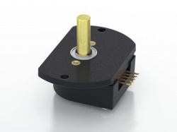
Rotary encoders are devices that generate electrical pulses as they rotate. The angle or rate of rotation that the encoder is experiencing can be measured by monitoring the number or frequency of the pulses. In robotics, encoders are commonly attached to the robot's drive motors and used to measure the robot's linear speed, angular speed, and distance traveled.
Measurement: When attached to the drive motors, measures wheel speed. This information can then be used to track the robot’s linear and angular/rotational speed and subsequently the robot’s position and heading by integrating the data over time
Ideal operating conditions: Robot operating on smooth/even ground where wheels maintain constant rolling contact with no slip.
Sensor Pros:
- Quite accurate over short time periods/distances
- Works indoors and outdoors, day or night
- Good for mitigating discrete jumps in position and orientation when fused with other sensors
- Great fallback sensor when things go wrong
- Can be used for closed loop speed control of the wheels
Sensor Cons:
- Requires initial calibration between encoder counts and amount of robot movement
- Assumes no slip between robot wheel and ground. An unstable or inconsistent surface beneath the robot can lead to wheel slippage. Skid-steer robots also experience wheel slippage while turning. This causes error in the estimated robot position because the wheel moves but the robot doesn’t.
- Position errors from wheel slippage and imperfect calibration accumulate over time/distance to give a progressively worse position estimate. When used to measure speed instead of position this is less of an issue.
- Additional electronics are often needed to keep track of the encoder counts. However, some motor controllers (such as Roboteq models) have this functionality built-in.
Inertial Measurement Unit (IMU)
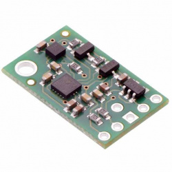
The IMU is typically a combination of three sensors: accelerometer, gyroscope, and magnetometer.
Measurement: Linear acceleration (accelerometer), angular velocity (gyroscope), heading (magnetometer/compass). 3D orientation (roll/pitch/yaw) when values are combined using sensor fusion techniques.
Ideal operating conditions: Can be used in nearly any conditions. Magnetometer needs to avoid EM noise and ferrous materials.
Sensor Pros:
- Can be used in nearly any conditions – indoor/outdoor, day/night, uneven surfaces. Requires few assumptions to use. This versatility makes the IMU a useful addition to any sensor setup.
- Good for mitigating discrete jumps in position and orientation measurement when fused with other sensors.
- Useful in both 2D and 3D applications.
- Produces a reasonable 3D orientation estimate.
- Acceleration measurements can be integrated to estimate velocity and position. However, these estimates are noisy and will accumulate error over time. Fusing the acceleration data with other sensors is a better approach.
- Very inexpensive. Decent IMUs are available for less than $20.
Sensor Cons:
- Requires initial calibration
- It is difficult to work directly with raw IMU data due mainly to noise. Filtering algorithms are needed to extract useful information. Higher end IMUs can filter the data before outputting it.
- Gyroscopes are susceptible to drift.
- Magnetometer/compass output is unreliable. Must be corrected based on where it is being used in the world. Even then the compass heading is inaccurate (+-20 degrees or worse). Also vulnerable to external magnetic sources.
GPS
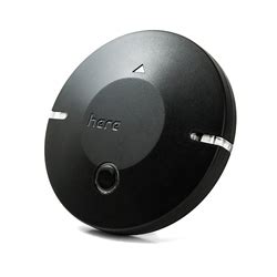
Measurement: GPS receiver exchanges data with GPS satellite system to obtain time and location information anywhere on the planet. For basic GPS the position accuracy is about 10-20 meters. WAAS can reach an accuracy of under 3 meters and RTK can reach 1 cm.
Ideal operating conditions: Outdoors with an unobstructed view of the sky. Does not work indoors! WAAS only works in the US and requires a nearby public reference station to feed it correctional data. RTK requires sky visibility in a cone at an elevation of ~30 degrees to the horizon and a base station setup very close by for corrections.
Sensor Pros:
- Data is easily processed, allowing the use of cheaper microcontrollers
- Can receive positioning data anywhere in the world (while outside) with no setup. This is a huge positive.
- WAAS and RTK can have decent accuracy with some extra setup
Sensor Cons:
- Slow update rate
- Only works outside
- Generally not accurate enough by itself to be used for robot navigation
- WAAS has reasonable accuracy but only works in the US
- While RTK has impressive accuracy, it is difficult to setup and get working reliably in real-time
- Difficult to align with map data
Marvelmind Indoor Positioning System (IPS)
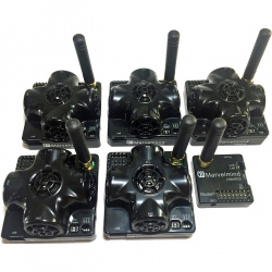
This is a positioning system that uses a set of stationary ultrasonic beacons to track the position of a mobile beacon attached to the robot.
Measurement: Position in 3D space.
Ideal operating conditions: Can be used in nearly any conditions.
Sensor Pros:
- Directly provides accurate 3D position data (about 1-2” error) with no additional data processing required. This is a big deal since generating reliable position data is one of the main goals of the robot’s positioning system (you still need orientation though).
- No computational load is required from the robot which allows the use of a less powerful microcontroller.
- Despite the name, can be used outdoors.
Sensor Cons:
- Setup required. Must place stationary beacons beforehand which limits portability of the robot. Marvelmind PC software and stationary beacon self-arrangement algorithm make it so setup isn’t too much of a hassle though.
- Beacons have batteries that must be recharged from time to time.
- Position is subject to discrete jumps. Fusion with encoder or imu measurements helps with this.
- Line of sight requirements are hard to meet in a cluttered environment.
- Susceptible to interference from other sources of ultrasonic noise.
Simple Obstacle Detection Sensors
These sensors are able to detect obstacles at a point, in a line, or in a small cone. Some may also be used as one-dimensional positioning sensors, e.g. to track the distance between the robot and a wall.
Contact/Bumper/Limit Switches
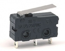
Obstacle Detection: This is a simple switch that is positioned on the robot such that it is tripped when the robot hits an obstacle. Output is usually a simple high/low digital signal.
Ideal operating conditions: Can be used in any conditions. The only consideration is where to place it on the robot.
Sensor Pros:
- Can be used in any conditions
- Simple to interface with code. Just read a digital signal!
- Reliable due to simplicity. There’s not much that can go wrong.
- The above points make the contact switch a great failsafe option.
Sensor Cons:
- Doesn’t detect an obstacle until the robot has already hit it.
- May require some mechanical adjustment to make sure it trips correctly without giving false positives.
IR Distance Sensors and 1D Lidars
Obstacle Detection: Detects obstacles in a straight, narrow beam of light. Lidar will be more accurate (and expensive) than simple IR sensors. IR sensors have a decent detection range (maybe 10-15 ft max) while Lidars that detect out to 60+ feet are common.
Ideal operating conditions: IR sensors and Lidars can both become erratic when exposed to sunlight interference. Some sensors will work perfectly outside while others may be fine with ambient sunlight and have problems only when pointed towards the sun. The rest range from slightly noisy to completely unusable outside.
Sensor Pros:
- Data is easily processed, allowing the use of cheaper microcontrollers
- Less expensive than 2D Lidar
- Good detection range and update rate
- 1D Lidar has good accuracy
- Can be used for 1D positioning or following applications
Sensor Cons:
- IR sensors often have discontinuous, nonlinear, and/or noisy output.
- Only detects obstacles in a narrow beam. If these are the primary obstacle detection sensors on a robot then several of them are required and there will still be big gaps in the detection zone – between the beams and above/below them.
- You may be tempted to sweep the sensor using an RC servo or something, but this generally doesn’t work very well. You’re better off buying a cheap 2D lidar at that point.
- These sensors can be vulnerable to dirt/dust and scratches.
Ultrasonic Distance Sensors
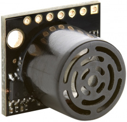
Obstacle Detection: Ultrasonic Distance Sensors detect obstacles in a cone. Although the detection area is significantly larger than IR and 1D lidar, the ultrasonic sensor still only measures the distance to the closest object. Maximum detection range is about 15 feet.
Ideal operating conditions: No sources of external ultrasonic noise present.
Sensor Pros:
- Data is easily processed, allowing the use of cheaper microcontrollers
- Inexpensive
- Good detection range and update rate
Sensor Cons:
- Ultrasonic emissions can echo, causing the receiver to pick up “ghost” data
- Similarly, complications can arise if multiple ultrasonic sensors are used since receivers can pick up emissions from other sensors. Some effort may be required to coordinate the emit/receive measurement times for each sensor.
Advanced Obstacle Detection Sensors
The sensors in this section can detect obstacles in 2 or 3 dimensions and are capable of generating maps of the environment.
2D Lidar
Obstacle Detection: Detects obstacles surrounding the robot. The 2D lidar generates a ring of points that extend to the closest obstacle in all directions. Able to create a rough map of the robot’s immediate surroundings.
Ideal operating conditions: Installed at a height where obstacles are expected to be encountered. Some Lidars are sensitive to sunlight, depending on the specific model and design.
Sensor Pros:
- Less data to process than a 3D Lidar
- Much more coverage than 1D sensors like IR and 1D Lidar
- Can be used to generate a 2D map and utilize 2D SLAM
- Good detection range and update rate
Sensor Cons:
- Can only see obstacles on a single horizontal plane, unable to see above and below the sensor
- More data than 1D sensors, usually requiring a small computer to use
- Unreliable when the robot pitches and rolls, due to the detection plane intersecting the ground
3D Lidar
Obstacle Detection: Detects obstacles surrounding the robot in 3D space. The 3D lidar generates a cloud of points that extend out from the sensor in all directions horizontally and 30 degrees above and below the sensor vertically. Able to create a detailed map of the robot’s surroundings, including obstacles above the robot and below the lidar.
Ideal operating conditions: Installed on the top of the robot, low enough to the ground where the 30 degree window is able to see the area directly in front of the robot. Some Lidars are sensitive to sunlight, depending on the specific model and design.
Sensor Pros:
- Full coverage of the robot’s environment
- Can be used to generate a 3D map and utilize 3D SLAM
- Reliable due to the large number of data points to base position off of
- Works in 3D environments where the robot is pitching, rolling, and changing in elevation. Can generate 3D position and orientation estimates.
- Can detect obstacles above and below itself, which a 2D lidar would miss.
Sensor Cons:
- Expensive
- Generates a large amount of data, which requires a more powerful computer to process and make use of
- Limited viewing angle, restricts where the sensor can be placed effectively
