Difference between revisions of "Encoders"
(→Sensor Overview) (Tag: Visual edit) |
(Redirected page to Encoder Support) (Tags: New redirect, 2017 source edit) |
||
| Line 1: | Line 1: | ||
| + | #REDIRECT [[Encoder Support]] | ||
| + | |||
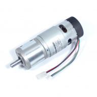
[[File:TD-044-078 ig42 motor encoders.jpg|thumb|191x191px|The encoder is inside the black end cap. Extra wires are present that connect with the encoder.]] | [[File:TD-044-078 ig42 motor encoders.jpg|thumb|191x191px|The encoder is inside the black end cap. Extra wires are present that connect with the encoder.]] | ||
Rotary encoders are devices that generate electrical pulses as they rotate. The angle or rate of rotation that the encoder is experiencing can be measured by monitoring the number or frequency of the pulses. In robotics, encoders are most commonly attached to the robot's drive motors and used to measure the robot's linear speed, angular speed, and distance traveled. Drive motor encoders can also be used to perform [[Speed Control#Closed Loop|closed loop speed control]] on the wheels. More generally, encoders can be attached to any of the robot's joints to track its speed and/or angle, such as a rotating joint in a robotic arm. | Rotary encoders are devices that generate electrical pulses as they rotate. The angle or rate of rotation that the encoder is experiencing can be measured by monitoring the number or frequency of the pulses. In robotics, encoders are most commonly attached to the robot's drive motors and used to measure the robot's linear speed, angular speed, and distance traveled. Drive motor encoders can also be used to perform [[Speed Control#Closed Loop|closed loop speed control]] on the wheels. More generally, encoders can be attached to any of the robot's joints to track its speed and/or angle, such as a rotating joint in a robotic arm. | ||
Latest revision as of 15:25, 16 April 2021
Redirect to:
Rotary encoders are devices that generate electrical pulses as they rotate. The angle or rate of rotation that the encoder is experiencing can be measured by monitoring the number or frequency of the pulses. In robotics, encoders are most commonly attached to the robot's drive motors and used to measure the robot's linear speed, angular speed, and distance traveled. Drive motor encoders can also be used to perform closed loop speed control on the wheels. More generally, encoders can be attached to any of the robot's joints to track its speed and/or angle, such as a rotating joint in a robotic arm.
Contents
Sensor Overview
Measurement: Motor rotation distance. When attached to the drive motors, used to measure wheel speed and distance.
Ideal operating conditions: Robot operating on smooth/even ground where wheels maintain constant rolling contact with no slip.
Sensor Pros:
- Quite accurate over short time periods/distances
- Works indoors and outdoors, day or night
- Good for mitigating discrete jumps in position and orientation estimates when fused with other sensors
- Great fallback sensor when things go wrong
- Can be used for closed loop speed control of the wheels
Sensor Cons:
- Requires initial calibration between encoder counts and amount of robot movement
- Assumes no slip between robot wheel and ground. An unstable or inconsistent surface beneath the robot can lead to wheel slippage. Skid-steer robots also experience wheel slippage while turning. This causes error in the estimated robot speed and position because the wheel moves but the robot doesn’t.
- Position errors from wheel slippage and imperfect calibration accumulate over time/distance to give a progressively worse position estimate. When used to measure speed instead of position this is less of an issue.
- Additional hardware is often needed to keep track of the encoder counts. However, some motor controllers (such as Roboteq models) have this functionality built-in.
Encoder Output
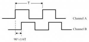
Encoders typically output what is known as a quadrature signal. A quadrature signal is comprised of two channels (Channel A and Channel B). Channel B is 90 degrees out of phase from channel A. This allows the circuitry watching the output signal to know what direction you are traveling. If B trails A then your motor is moving clockwise, if A trails B then your motor is moving counter clockwise.
Adding Encoders to a Robot
We have written a practical guide on this topic here.
Quick Links to our Encoders and Accessories:
Encoder Buffer and Pull-up Boards:
- Dual LS7366R Quadrature Encoder Buffer Breakout Board (TE-183-002)
- Kangaroo x2 motion controller (TE-180-000)
- IG32, IG42, and IG52 Gear Motor Encoder Pull-up Board (TE-179-000)
Motors with Encoders:
- IG42 24VDC 013 RPM Gear Motor with Encoder (TD-044-013)
- IG52-04 24VDC 082 RPM Gear Motor with Encoder (TD-045-082)
- IG32P 24VDC 075 RPM Gear Motor with Encoder (TD-055-075)
- IG32 24VDC 074 RPM Gear Motor with Encoder (TD-054-074)
- IG42 24VDC 078 RPM Gear Motor with Encoder (TD-044-078)
- IG32P 24VDC 265 RPM Gear Motor with Encoder (TD-055-265)
- IG32P 24VDC 190 RPM Gear Motor with Encoder (TD-055-190)
- IG32 24VDC 191 RPM Gear Motor with Encoder (TD-054-191)
- IG52-04 24VDC 010 RPM Gear Motor with Encoder (TD-045-010)
- IG52-04 24VDC 136 RPM Gear Motor with Encoder (TD-045-136)
- IG42 24VDC 122 RPM Gear Motor with Encoder (TD-044-122)
- IG52-04 24VDC 285 RPM Gear Motor with Encoder (TD-045-285)
- IG42 24VDC 240 RPM Gear Motor with Encoder (TD-044-240)
Motor Controllers with direct encoder feedback:
- SyRen 50A Regenerative Motor Driver (TE-098-150) with Kangaroo Option
- RoboteQ SDC2150 - 2x20A 50V Motor Controller with Encoder Input (TE-144-050)
- RoboteQ SDC2130 - 2x20A 30V Motor Controller with Encoder Input (TE-144-030)
- RoboteQ XDC2460 - 2x150A 60V Motor Controller with Encoder Input (TE-286-150)
- RoboteQ MDC2460 - 2x60A 60V Motor Controller with Encoder Input (TE-240-060)
- RoboteQ MDC2230 - 2x60A 30V Motor Controller with Encoder Input (TE-240-030)
- SyRen 25A Regenerative Motor Driver (TE-098-125) with Kangaroo Option
- SyRen 10A Regenerative Motor Driver (TE-098-110) with Kangaroo Option
- Sabertooth Dual 25A Motor Driver (TE-091-225) with Kangaroo Option
- Sabertooth Dual 60A motor driver (TE-091-260) with Kangaroo Option
Encoder support:

